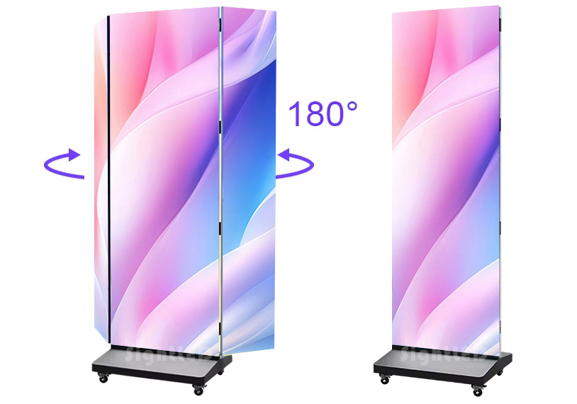
For years, the LED poster has been the secret weapon of retailers, event planners, and museums. They are slim, standalone, and easy to wheel into place. But the real magic happens when you stop treating them as islands and start treating them as building blocks.
Today, Sight LED will guide you how to turn multiple LED posters into one massive, seamless screen.
Why Splice Posters Instead of Buying a Giant LED Wall?
If you want a giant screen, why not just buy a giant LED wall? The answer lies in logistics, flexibility, and accessibility.
The Rigging Nightmare
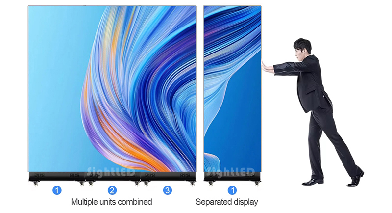
A traditional large-format LED wall requires a heavy-duty steel truss system, counterweights, and often a certified rigger. They hang from ceilings or ground-stack with massive base plates. However, LED display posters are floor-standing. They have integrated floor bases with wheels. You roll them in, plug them in, and they stand upright. Splicing them together creates a massive canvas without ever touching the ceiling or building a heavy structure.
The “Off-the-Shelf” Advantage
Custom LED walls require a complex quoting process involving pixel pitch calculators, exact cabinet counts, and custom flight cases. LED posters are a finished product. You order them by the unit. Need a bigger screen next month? Rent or buy two more units and line them up. The scalability is linear and simple.
Aesthetic and Safety
In high-end retail or historic venues, hanging heavy equipment is forbidden. Spliced LED posters sit flush on the floor, looking like part of the interior design. They are inherently low-profile and low-risk.
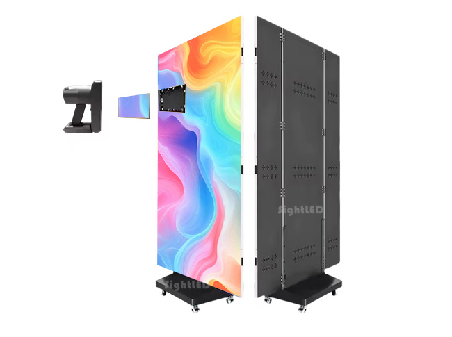
What Makes Seamless Splicing Possible?
You cannot seamlessly splice two standard LCD TVs. Even the thinnest LCD bezel creates a 3.5mm black line that shatters the illusion. LED display posters are different because of two specific engineering features:
Edge-to-Edge LED Design : LED posters have LEDs placed right up to the physical edge of the cabinet. The plastic or metal housing stops at the side, but the light emitting diodes go right to the border.
Pixel Pitch Matching: If you try to splice a P1.5 poster with a P2 LED poster, the pixel density won’t match, and the image will look distorted or scaled incorrectly at the seam.
When you place two posters side-by-side, the distance between the last pixel on Unit A and the first pixel on Unit B should mathematically equal the distance between any two adjacent pixels inside Unit A. Achieving this requires precision manufacturing and software calibration.
The Step-by-Step Guide to Flawless Splicing
Let’s get hands-on. Whether you are using Novastar, Linsn, or Colorlight processing systems, the workflow is universally applicable.
Step 1: Pre-Installation Alignmen
You cannot rely on the software alone to fix a crooked screen. The physical alignment must be near-perfect.
The Connection Plate: Most LED poster manufacturers, SightLED provide a specific side-locking mechanism or alignment pin. This is a metal bracket that slots into the side of the cabinet, locking them together at exactly the right depth and angle.
The Floor Check: Use a laser level. Ensure the floor is flat. If the floor slopes even 2mm, the tops of the posters will drift apart. Use the adjustable feet on the bottom of each poster to micro-adjust the tilt until the corners meet perfectly.
The Gap Check: There should be zero air gap. The metal housings should touch. If you see light leaking from between the cabinets, you have a misalignment issue, not a software issue.
Step 2: Signal Flow
You have multiple screens, but you want one image. How does the video get distributed?
Method A: Loop-Out Daisy Chain
Connect your video source (a media player or laptop) via HDMI to Poster #1.
Connect an Ethernet cable (Cat5e/Cat6) from the “Output” or “Loop” port of Poster #1 to the “Input” port of Poster #2.
Connect Poster #2’s Output to Poster #3, and so on.
So, Poster #1 receives the full 4K image. It “slices off” the portion it needs to display and passes the remaining data down the line.
Visualizing the Daisy Chain Connection Path:
The signal path for a standard seamless splicing setup should look like this:
[Media Player HDMI Output] —> [Poster 1: HDMI IN / Ethernet LOOP OUT] —(CAT6 Cable)—> [Poster 2: Ethernet IN / LOOP OUT] —(CAT6 Cable)—> [Poster 3: Ethernet IN]
Method B: The Central Processor Box
If you are splicing 6+ posters to create an ultra-wide landscape, the daisy chain bandwidth might bottleneck. Instead, You can use an external LED Video Processor, such as Novastar VX series or H-series.
The processor takes the single HDMI input and splits it into multiple Ethernet outputs, each feeding one or two posters directly.
Step 3: The Software Magic
This is the step where most first-timers get stuck. The posters don’t know they are neighbors; you have to tell them via the LED Novastar LCT.
Read the Receiving Cards: Connect your laptop to the USB port of the first poster and open the software. Click “Read from Receiving Card.” You will see the individual parameters of that specific poster cabinet, such as Width: 128px, Height: 256px.
Set the Total Screen Size: Navigate to the “Screen Configuration” or “Splicing Settings” tab.
Input the Layout Grid:
You are creating a virtual grid that matches your physical layout.
Example: You have 3 posters placed in a horizontal row.
Total Width: 3 x (Width of one poster).
Total Height: Height of one poster.
Map the Ports (The Crucial Part):
The software will show a diagram of Ethernet ports (Port 1, Port 2…).
You need to drag and drop the “Display Area” boxes onto the grid.
For a daisy chain: You will likely see only Port 1 active. You will assign the first 1/3 of the grid to “Receiver Card 1,” the second 1/3 to “Receiver Card 2,” and so on.
Pro Tip: Use the “Smart Setting” wizard if available. It flashes patterns on the screen to help you identify which physical cabinet is which in the software grid.
Adjusting the Seam Compensation:
Here is the secret sauce. Even with perfect physical alignment, the visual seam might still look like a single column of missing pixels due to the physical edge of the plastic housing.
Navigate to Advanced Settings > Image Cropping or Seam Adjustment.
You will see options for Start X and Width.
To make the image flow perfectly, you might need to overlap the content slightly or crop the edge columns of the video signal. This tricks the eye into seeing continuous motion across the bezel line. This is a trial-and-error process requiring you to stand back 10 feet and squint.
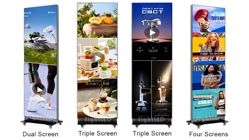
Content Strategy for Spliced Posters
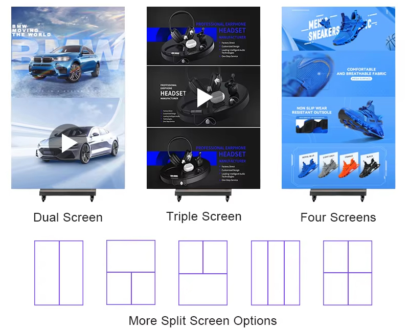
You have successfully built a giant 16:3 or 32:9 ultra-wide canvas. Now, what do you play on it?
Do NOT Play 16:9 Loops: If you play a standard widescreen video on this new canvas, it will either stretch and distort faces horribly, or it will be “pillarboxed” with giant black bars on the left and right. That defeats the purpose of the seamless splice.
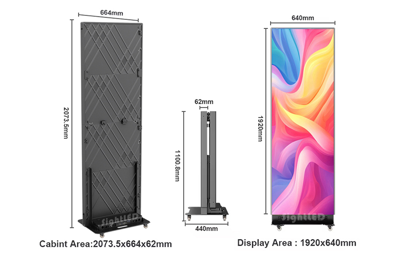
Render to Native Resolution: You must create content that matches the exact total pixel dimensions of your spliced array. For example:
1 Poster = 288 x 512 pixels.
3 Posters Horizontal = 864 x 512 pixels.
Render your video at exactly 864×512 resolution.
To assist with your content production planning, here is a quick reference chart for common LED poster video wall configurations.
| Configuration | Physical Setup | Total Canvas Resolution | Aspect Ratio | Ideal Content Type |
|---|---|---|---|---|
| Single Unit | 1 Poster | 288 x 512 | 9:16 (Portrait) | Vertical Shorts / Reels |
| Dual Spliced | 2 Posters Side-by-Side | 576 x 512 | 9:8 (Squarish) | Static Branding / Split Screen |
| Triple Spliced | 3 Posters in a Row | 864 x 512 | 27:16 (Ultra-Wide) | Panoramic Landscapes / Crawls |
| Quad Spliced | 2×2 Grid (4 Posters) | 576 x 1024 | 9:16 (Tall) | Portrait Cinema / Tall Totem |
| Hexa-Wide | 6 Posters in a Row | 1728 x 512 | 27:8 (Cinematic) | Immersive |
Leverage the Ultra-Wide Format: This format is cinematic. Use it for panoramic landscapes, long text crawls, or continuous product showcases. The content should move across the seam to hide the fact that it exists. A static image of a face split by a seam will still look slightly off; a moving car that glides from Screen 1 to Screen 2 will hide the seam completely.
Common Pitfalls and Troubleshooting
Even the pros face these issues. Here’s how to fix them.
Problem: The image is “Tearing” .
Cause: Genlock sync failure.
Fix: In the sending box software, ensure “Frame Synchronization” is turned ON. This forces all receiving cards to refresh their pixels at the exact same microsecond.
Problem: One poster is slightly brighter/darker than the others.
Cause: Factory calibration drift or aging LEDs.
Fix: Perform a Manual Brightness Adjustment. Lower the brightest screen to match the dimmest screen. Never try to increase brightness on old panels to match new ones; you’ll burn out the LEDs faster. Also, check the Color Temperature setting (6500K is standard) to ensure they match.
Problem: The seam looks like a thick black line.
Cause: The physical gap is too largeOR the pixel mapping has a “dead zone” where no content is being sent.
Fix: Re-check the floor leveling. Then, in software, check your “Virtual Screen Offset” settings. Sometimes, the software automatically adds a “gap” of a few millimeters to account for cabinet frames. You need to manually override this to 0mm.
Conclusion:
We have guide you how to splicie LED display posters. It takes the complexity out of structural engineering and puts the power back into the hands of the AV technician or the marketing manager. If you need this kind of large-scale LED poster screen, please feel free to contact us.
FAQs:
Can I splice LED display posters that have different pixel pitches,such as P1.8 with P2.5?
Technically, the receiving cards will accept the signal, but visually, it is not recommended. The pixel density is physically different. The image will appear larger and less detailed on the P2.5 panel, causing a scaling mismatch at the seam.
How many LED posters can I daisy chain via Ethernet loop-out?
The industry standard limit for a stable, tear-free daisy chain is typically 4 to 6 units when using a single 4K source. Exceeding this relies on the receiving card’s memory buffer. For installations of 8+ posters, you need an external NovaStar H-Series Video Processor to distribute signal to multiple ports simultaneously.
What specific software do I need for the seamless splicing setup?
The industry standard is NovaStar LCT , also branded as Nova LCT-Mars. You will also need the USB-to-RS232 or direct USB-B driver to read the receiving card parameters. Without access to this software, you cannot map the canvas grid or adjust seam compensation.
Does physically locking the cabinets together with the provided bracket guarantee a seamless image?
No. The physical bracket ensures alignment . The seamless visual flow is achieved only after you complete the Seam Adjustment in the software described in Part 5. You must both lock the hardware AND crop the software edge.