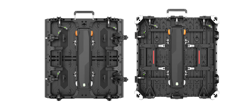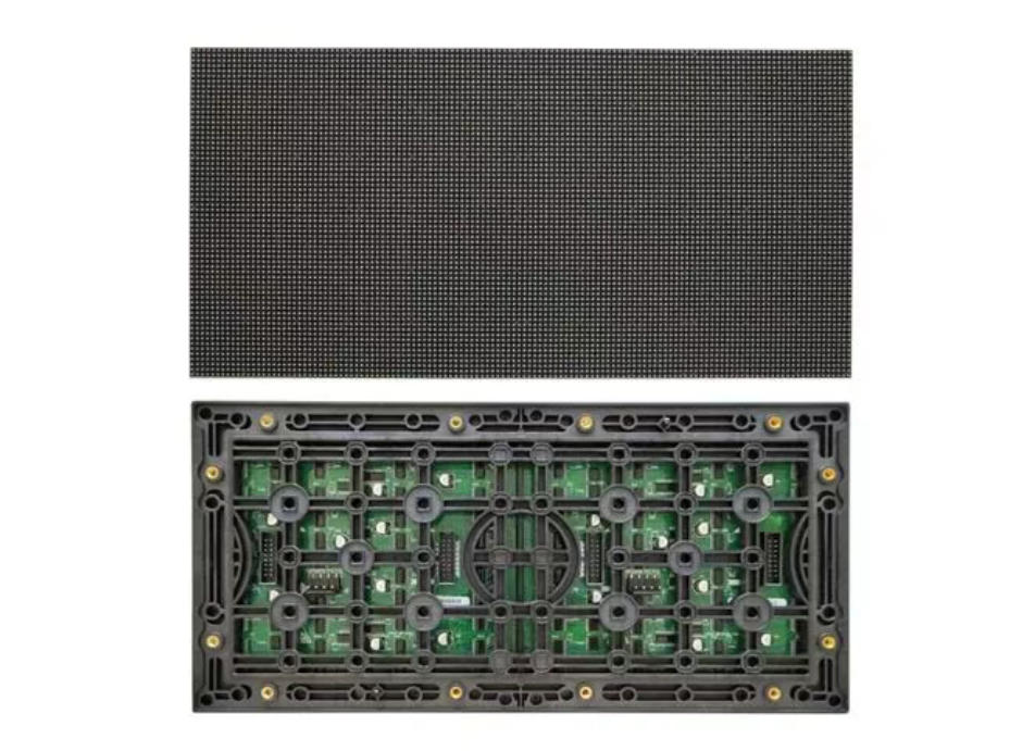
LED display module’s seamless performance relies on multiple components. We categorize these critical parts into four core groups:
- Core display components
- Drive control components
- Circuit connection components
- Structural protection components.
Each group plays an irreplaceable role. Below, we fuide you the key components, their features, and how they contribute to the module’s overall functionality.
Core Display Components:
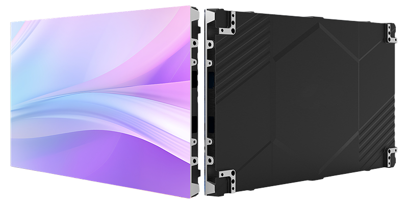
We convert electrical energy into light energy using LED light-emitting devices. These devices form the foundation of the module’s ability to produce vibrant, full-color images.
By adjusting the brightness of each color channel, we mix these three primary colors to create virtually any hue the human eye can perceive. This color-mixing principle is what enables regular or flexible LED modules to display vivid videos, images, and text for a wide range of applications.
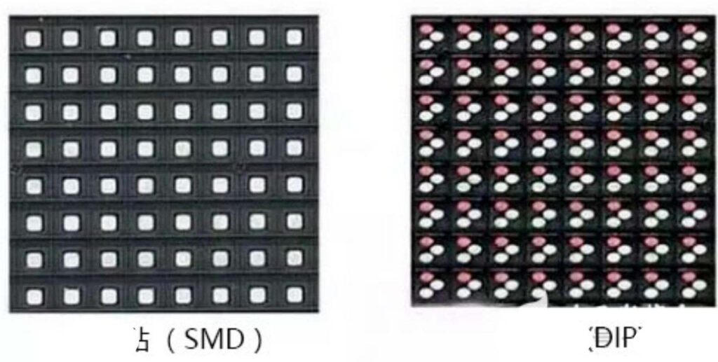
In practical applications, we mainly use two types of LED light-emitting devices: SMD LEDs and DIP LEDs. SMD LEDs are compact and lightweight. Therefore, they are ideal for high-resolution indoor displays . On the other hand, DIP LEDs feature a more robust structure and better heat dissipation. They are preferred choice for withstand harsh environmental conditions, such as extreme temperatures and heavy rainfall.
Module Identification Methods:
Before installing or maintaining an LED display module, we must first identify its key parameters. These parameters include model number, resolution, and compatibility requirements. We use three reliable methods to get this information:
- Checking module labels
- Conducting physical inspections
- Measuring circuit parameters.
First, we start with the module’s label. LED display Manufacturers attach paper or metal labels to each module before leaving the factory. These labels consolidate core information, including the brand name, production date, batch number, and the all-important “size + pixel pitch” specification.
We use the batch number and production date for quality traceability and warranty verification. We also judge the module’s age, which helps assess its remaining service life.
However, labels can get worn out or lost over time due to installation, transportation, or long-term use. When that happens, we turn to physical observation and measurement to reverse-engineer the key parameters.
The most critical measurement here is the pixel pitch, also known as the “P-value”. To calculate this value, we use a ruler to measure the distance between the centers of two adjacent LED beads in millimeters.
For example, a 2.5 mm measurement means we use a P2.5 module. We also count the number of LED beads horizontally and vertically. Then we calculate the module’s resolution by multiplying the horizontal bead count by the vertical bead count. This simple yet effective method . It can confirm the module’s specifications even without a label.
Circuit Connection Components:
Circuit connection components act as the bridges that transmit power and control signals between the LED module and external systems. Without these components, the module’s internal chips and LEDs would not receive the energy and instructions. We focus on two key connection components here:
- pin headers with surface-mount ox-horn connectors
- VH-4 power connectors.
Pin Headers with Surface-Mount Ox-Horn Connectors
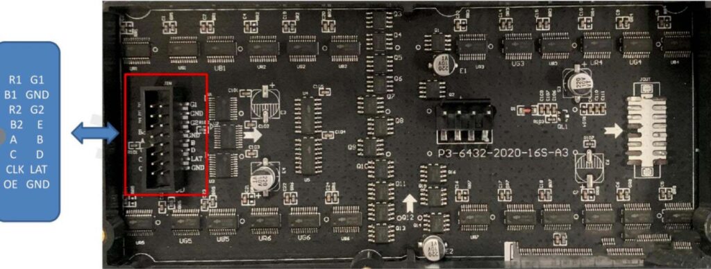
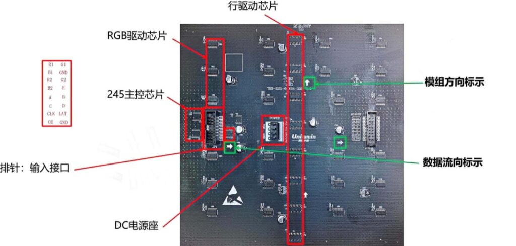
We use pin headers paired with surface-mount ox-horn connectors to transmit control signals for the LED module. These pin headers are “pin-shaped plugs” . we solder to both ends of the signal cable, or to the corresponding position of the ox-horn connector on another module. The pin header and ox-horn connector fit together precisely. When inserted, the metal pins conduct electricity and establish a stable signal connection.
These components serve as the signal input and output ports on both ends of the module. They ensure that control signals are transmitted smoothly to the module’s drive chips.
VH-4 Power Connectors
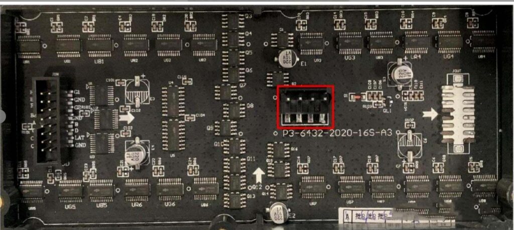
The VH-4 power connector is the primary component. It links the power cable to the module’s printed circuit board (PCB). It is a 4-pin through-hole power connector. It features a durable plastic housing and metal pins. We solder it directly to the module’s PCB to connect external power cables, which are commonly 2-core or 4-core cables.
The name “VH-4” has a clear meaning: “VH” refers to the connector series, while “4” indicates the number of pins. The core function of this connector is to supply power to the module’s chips and LED beads.
A reliable VH-4 connector provides a steady power supply. It can directly impact the module’s brightness stability and service life.
Drive Control Components:
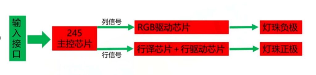
Drive control components are the “brains” of the LED display module. They process control signals, manage power distribution, and coordinate the work of each LED bead to produce accurate images. We use a variety of specialized chips in this category, each with a distinct role in the system.
245 Main Control Chip
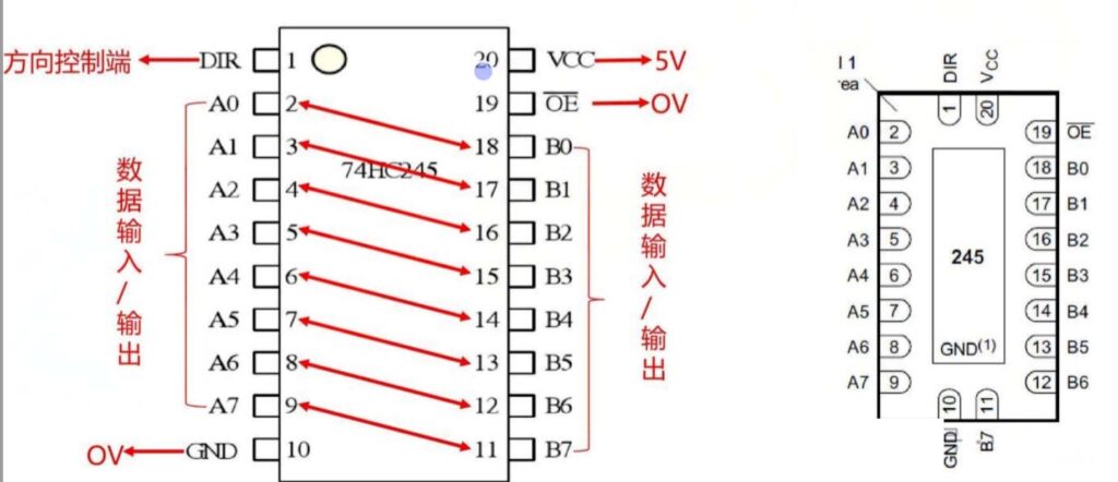
The 245 main control chip is a key relay station for signal transmission. Almost all input signals pass through this chip before reaching other components. Its core value lies in three critical functions:
- Amplifying weak signals
- Correcting distorted signals
- Protecting the front-end circuit.
Without the 245 chip, control signals would struggle to reach the drive chips stably. The module would display anomalies like missing pixels or garbled images.
The chip has 8 input pins and 8 output pins. It receives signals through the input pins, processes them uniformly, and sends identical processed signals out through the output pins.
RGB Drive Chip
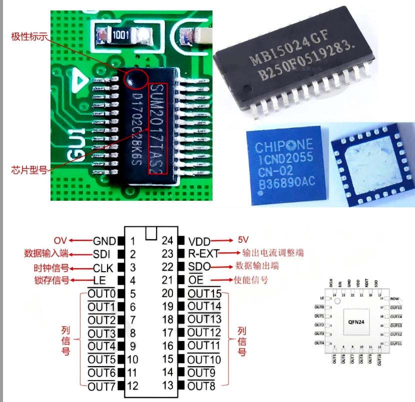
RGB drive chips can control the red, green, and blue LEDs in each pixel. These three color LEDs are all connected to the negative electrode of the LED bead. The RGB drive chip uses data, clock, latch. It enables signals to manage the LED columns on the module. This column-based management can control each column independently. It is essential for displaying dynamic images and videos.
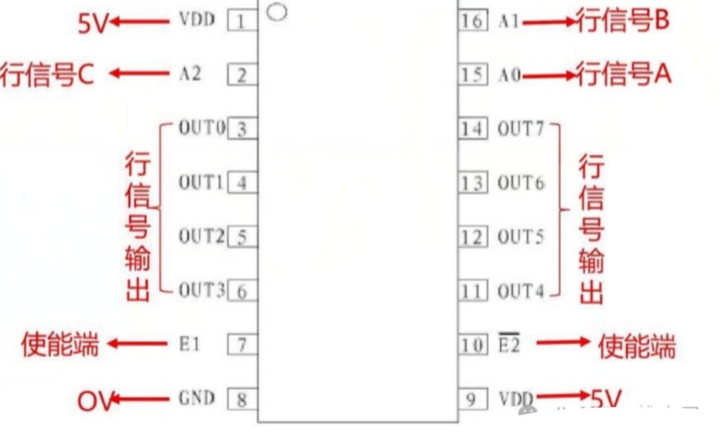
Row Decoder Chips (138 and 139)
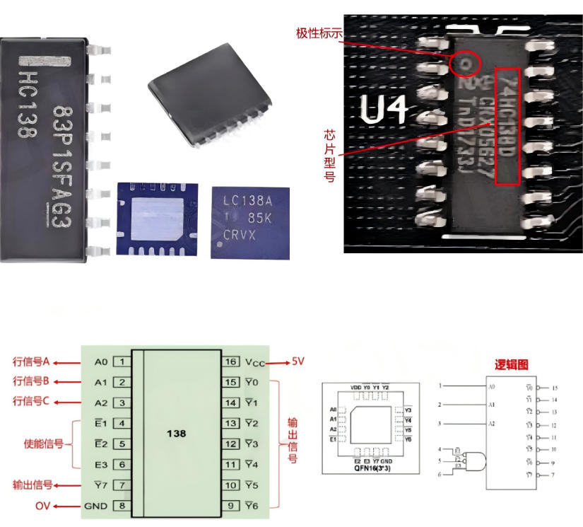
Row decoder chips are responsible for managing the module’s row data. We use two common types: the 138 chip and the 139 chip.
The 138 chip is a binary-to-decimal, 3-line to 8-line decoder. We use it to decode ABC row signals and transmit them to the row drive chips. It then works with row drive chips to control the positive electrodes of the LED beads. It can enables the scanning display function for large-scale LED screens.
By contrast, The 139 chip consists of two independent 2-line to 4-line decoders. We use it alongside the 138 chip to decode DE row signals and transmit them to the row drive chips. This combination expands the module’s row control capabilities, making it suitable for higher-resolution displays.
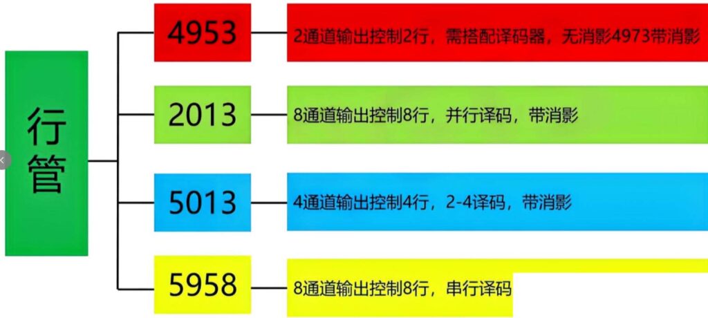
Row Drive Chips (4953 and 4973)
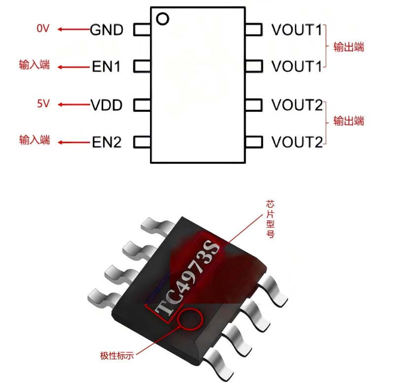
Row drive chips act as the power switches . It can control the positive electrodes of the LED beads. We commonly use two models: the 4953 and 4973 chips.
Each 4953 chip can drive 2 rows of LED beads. It functions as a row driver and power transistor, providing stable power to the designated rows. The 4973 chip also drives 2 rows of beads per chip, but it has a different pin definition compared to the 4953. Most importantly, it includes a shadow-elimination function. It can eliminate the ghosting effect.
Integrated Row Decoder Drive Chips
To simplify circuit design and improve performance, we have developed integrated row decoder drive chips. These chips combine the decoding function of the 138 chip, the row management function of the 4953 chip, and the shadow-elimination function into a single component.
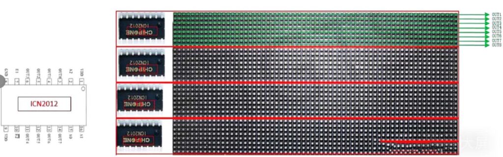
Common integrated models include the 2012, 2013, 7258, 7268, and 5166 chips. All are 3-line to 8-channel decoders. They streamline PCB layout and reduce the number of components needed, which lowers production costs and improves module reliability.
SPL5013 Row Decoder Drive Chip
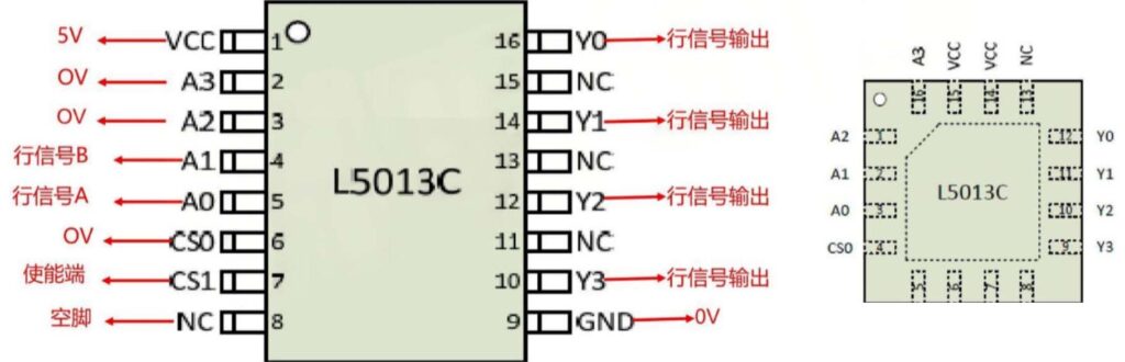
The SPL5013 is a specialized integrated row decoder drive chip with a 2-line to 4-channel design. Like other integrated chips, it combines decoding, row driving, and shadow-elimination functions. Its output pins connect directly to the positive electrodes of the LED beads.
We can easily achieve 1/8 or 1/16 scan duty cycles by cascading multiple SPL5013 chips. Therefore, it is suitable for a wide range of module sizes and resolutions. The built-in shadow-elimination function further enhances image quality by preventing ghosting.
Serial Decoder Drive Chips
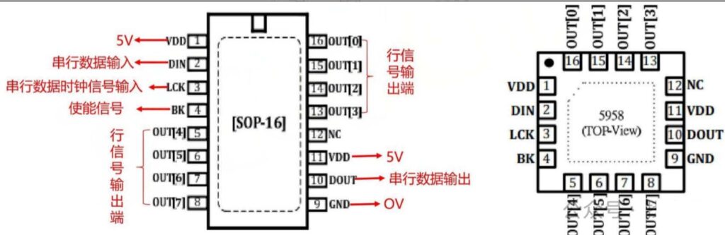
Serial decoder drive chips take integration a step further. They combine serial decoding circuits, power PMOS transistors, and shadow-elimination functions into one compact component. Most models offer 8-channel outputs, with pins that connect directly to the LED beads’ positive electrodes.
These chips completely replace the traditional 3-to-8 decoders ,such as the 74HC138 chip. We use them to simplify PCB wiring complexity significantly. It can reduce the risk of signal interference. They also boost the display’s overall image performance. Common serial decoder drive chips include the 5958, 2018, 2019, and 9736 models.
Basic Electronic Components:
Beyond the specialized components above, basic electronic components, such as resistors and capacitors. It plays a vital role in maintaining the module’s stability and longevity. These small, low-cost parts are the unsung heroes to ensure all other components work within their safe operating ranges.
Resistors
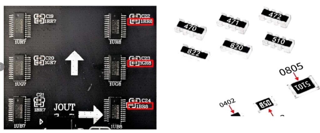
We refer to resistors as the “current controllers” and “circuit protectors” of the LED module. They perform three core functions:
- Setting constant current
- Limiting current for protection
- Voltage division matching.
These functions ensure that both the LED beads and chips operate within a safe current range. This directly impacts the uniformity of the display’s brightness and the module’s overall service life.
In circuit design, resistors are critical for determining the output current of 16-bit constant current ICs. We use individual resistors or resistor networks to regulate voltage or limit current. Even a small error in resistor value can lead to uneven brightness or premature component failure.
Capacitors
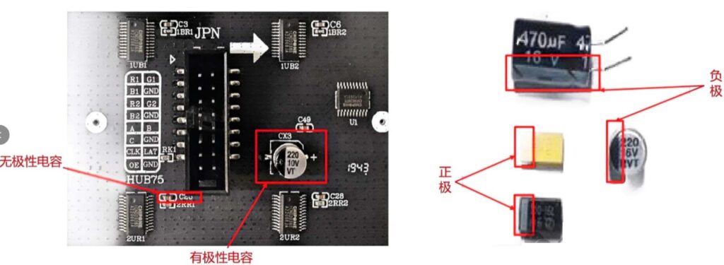
We call capacitors the “power stabilizers” and “signal purifiers” of the module. Their three key functions are filtering, decoupling, and energy storage. These functions create a stable electrical environment for the chips and LED beads. It can shield them from voltage fluctuations and signal noise.
In circuit design, capacitors block direct current while allowing alternating current to pass through. In pixel-level LED products, we mainly use capacitors for filtering purposes . By filtering out unwanted noise from the power supply and signal lines, capacitors ensure that the module delivers clear, flicker-free images.
Conclusion
Every component in an LED display module plays a specific and critical role. We design these components to work in harmony, turning electrical signals into stunning visual displays. If you can know how each part functions , you can select the right modules for specific applications. Whether you are designing a new LED screen or troubleshooting an existing one, we will help you achieve the best possible results.